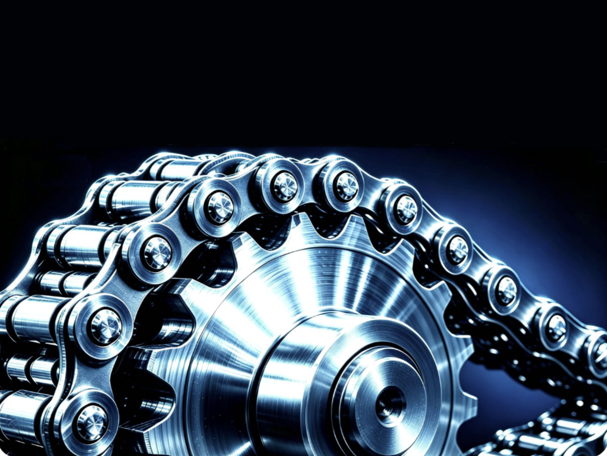
Chain drive systems are widely utilized in continuous-duty industrial applications, including mining conveyors, heavy equipment, and textile machinery. The alignment precision of sprocket coaxiality and coplanarity directly dictates engagement stability, fatigue service life, and total lifecycle operation and maintenance (O&M) costs. Addressing common industrial issues—such as coarse alignment practices, ambiguous tolerance criteria, unclarified failure mechanisms, and the inadequate precision of conventional calibration methods—this study systematically investigates the multi-stage degradation mechanisms triggered by sprocket angular misalignment. It quantifies fault evolution across specific deviation thresholds, establishes a comparative performance framework between traditional manual methods and precision laser alignment technology, and validates the operational value of precision alignment through industrial comparative trials.
The findings indicate that the safe allowable angular misalignment range for chain drives is 0.1° to 0.2°. Exceeding this threshold induces parasitic lateral side loads and localized stress concentrations, sequentially triggering unilateral tooth flank wear, pin-bushing articulation binding, and link plate plastic deformation, which can culminate in catastrophic chain breakage and unplanned outages under extreme operating conditions. Precision laser alignment achieves an angular resolution down to 0.1°, effectively eliminating parasitic loads, extending component service life by over 50%, and significantly mitigating unplanned downtime risks. This research provides a theoretical foundation and engineering reference for standardized assembly, failure diagnosis, and the establishment of high-precision O&M frameworks for industrial chain drives.
1. Industrial Applications of Chain Drives and Current Alignment Practices
Chain drive systems offer constant transmission ratios, high load-carrying capacity, and robust environmental adaptability, making them a primary mode of mechanical power transmission across continuous industrial operations. Shaft parallelism and sprocket coplanarity serve as vital assembly metrics that govern chain-sprocket engagement geometry and load distribution uniformity. Consequently, they exert a decisive influence on dynamic stability, fatigue degradation rates, and long-term operating reliability.
Field maintenance data indicates that over 70% of premature chain wear, joint binding, tooth climbing, and catastrophic chain breakages do not originate from baseline material fatigue. Instead, they stem from non-standard engagement conditions induced by prolonged sprocket misalignment. Even minor angular deviations continuously impose dynamic lateral thrust loads, accelerating alternating stress accumulation and structural fatigue wear.
Currently, conventional assembly practices—such as string-line verification, straightedges, visual estimation, and empirical trial-and-error adjustments—remain prevalent across many manufacturing facilities. These methods cannot reliably detect micro-angular misalignments under 0.2°. As a result, transmission systems often run under latent failure conditions, leading to cumulative structural damage that eventually causes equipment downtime and production losses. Addressing these engineering challenges, this study delineates the tiered failure mechanisms of sprocket misalignment, benchmarks calibration performance across methodologies, and substantiates the industrial efficacy of precision laser alignment.
2. Core Definitions of Sprocket Alignment and Industrial Tolerance Standards
2.1 Technical Definition of Sprocket Alignment
Sprocket alignment is a critical assembly and commissioning process. Its objective is to ensure that the driver and driven sprocket shafts remain parallel and their reference face planes remain coplanar. This geometric alignment ensures uniform chain engagement across the pitch line and smooth load transfer. Under nominal alignment conditions, loads are evenly distributed across the chain links, pins, and bushings without parasitic lateral forces, allowing the drive to sustain peak mechanical efficiency and minimal wear rates.
When axial angular misalignment or coplanar offset occurs, the theoretical path of the chain deviates. This introduces localized eccentric loading and stress concentrations, accelerating progressive fatigue degradation and steadily eroding operational reliability.
2.2 Industrial Standards for Allowable Angular Misalignment
According to mechanical design standards and industrial equipment assembly specifications, the safe allowable angular misalignment for chain drives under steady, continuous duty is 0.1° to 0.2°.
- Deviation < 0.2°: Parasitic side loads remain within the elastic fatigue endurance limit of the material, resulting in no measurable macro-level wear.
- Deviation > 0.2°: Internal contact stresses within the kinematic pair escalate sharply, causing wear rates to increase exponentially.
- Deviation > 0.5°: Irreversible kinematic interference occurs during engagement, inducing structural transmission failures that compromise plant operational safety.
3. Sprocket Misalignment Severity Levels and Progressive Failure Mechanisms
Transmission degradation driven by sprocket misalignment exhibits distinct progressive and tiered characteristics. As angular offset increases, lateral forces and engagement errors intensify, transitioning benign micro-wear into irreversible structural failure. Based on angular deviation thresholds, this study classifies misalignment into three distinct severity levels, systematically elucidating the failure symptoms and mechanical degradation mechanisms associated with each stage.
3.1 Mild Misalignment (< 0.2°): Latent Stress Concentration and Unilateral Flank Wear
Mild misalignment (< 0.2°) falls near the acceptable engineering threshold and rarely produces perceptible vibration, abnormal noise, or mechanical binding. Consequently, it remains largely undetected during routine walk-around inspections.
Slight angular offset causes the chain to engage the sprocket teeth asymmetrically. The transmission load concentrates on one side of the tooth profile, creating localized stress points. Over prolonged operation, cyclic contact stress causes ongoing abrasive and adhesive wear, manifesting as unilateral tooth flank gouging and minor link plate deformation. This continuous wear diminishes the component's fatigue life and represents the primary root cause of premature transmission degradation.
3.2 Moderate Misalignment (0.2°–0.5°): Articulation Binding and Cyclic Impact Loading
When angular offset exceeds the 0.2° threshold, lateral thrust loads rise substantially, taking up the internal clearance between the pin and bushing. This restriction increases rotational friction in the chain joint, restricts articulation flexibility, and impairs overall kinematic smoothness.
The skewed engagement profile creates mechanical interference during tooth entry and exit, triggering frequent tooth climbing, chordal action instability, and cyclic engagement impacts. Vibration and acoustic emissions increase noticeably, accompanied by a drop in mechanical efficiency. Under these conditions, wear rates reach 3 to 5 times nominal levels, accelerating structural fatigue accumulation and shortening maintenance intervals.
3.3 Severe Misalignment (> 0.5°): Plastic Deformation and Catastrophic Transmission Failure
Severe misalignment (> 0.5°) subjects the chain drive to heavy, continuous lateral loading. This forces inner link plates to flex unevenly and causes plastic deformation in the link apertures, permanently altering the chain pitch. This triggers a destructive feedback loop: angular deviation widens → engagement error escalates → structural distortion worsens.
Under extreme misalignment, recurring tooth jumping and chain wedging occur. Dynamic shock loads rapidly breach the ultimate yield and fatigue limits of both chain and sprocket materials, resulting in severed links, fractured sprocket teeth, or sudden drive seizure. These catastrophic structural failures cause immediate production line stoppages, posing equipment safety hazards and substantial downtime costs.
3.4 Misalignment Fault Classification Summary
- Mild Misalignment (< 0.2°)
- Fault Symptoms: Unilateral tooth flank wear; unmonitored loss of service life.
- Failure Mechanism: Asymmetric meshing trajectory induces localized stress concentrations and continuous micro-abrasive wear; gradual link plate micro-straining accumulates, degrading the equipment's nominal fatigue life.
- Moderate Misalignment (0.2°–0.5°)
- Fault Symptoms: Joint binding; tooth climbing; pronounced vibration and noise; transmission efficiency degradation.
- Failure Mechanism: Lateral thrust takes up pin-bushing clearances, raising rotational friction; skewed entry/exit angles generate cyclic shock loads, accelerating structural fatigue accumulation.
- Severe Misalignment (> 0.5°)
- Fault Symptoms: Sprocket tooth jumping; chain binding/seizure; chain fracture; transmission system failure.
- Failure Mechanism: Continuous lateral forces cause plastic link deformation and permanent pitch elongation; a compounding cycle of misalignment leads to dynamic impact loads that trigger catastrophic transmission failure.
4. Comparison Between Conventional Alignment and Precision Laser Alignment
4.1 Technical Deficiencies of Conventional Manual Alignment
Traditional alignment methods rely on piano wire, straightedges, and visual inspection. These techniques are limited to detecting macro-level millimeter displacements and cannot resolve micro-angular deviations within 0.2°. They suffer from low resolution, poor repeatability, lack of quantitative validation, and zero measurement traceability.
In complex operating conditions—such as elevated catwalks, confined machine envelopes, or high-tonnage drives—manual methods pose safety hazards and provide limited operational access. They can only correct gross mechanical offsets, leaving latent fatigue drivers unresolved and falling short of modern, high-reliability plant maintenance standards.
4.2 Core Advantages of Precision Laser Alignment Technology
Precision laser alignment projects a true geometric reference datum plane, quantifying shaft parallelism and sprocket coplanarity to deliver visual, digital, and standardized alignment.
The G-PLUS Laser Alignment Tool utilized in this study holds CE certification and ATEX explosion-proof certification, qualifying it for harsh operating environments containing combustible dust, high ambient temperatures, or hazardous area classifications. With an angular measurement accuracy of 0.1°, the system detects micro-misalignments that manual methods cannot resolve. Furthermore, it supports in-situ, non-intrusive inspection without requiring machine teardown, improving alignment throughput, suppressing parasitic side loads, and ensuring dependable, long-term drive operation.
5. Industrial Field Application and Maintenance Value Analysis
Over a 12-month comparative field trial in an industrial processing facility, implementing precision laser alignment yielded the following operational improvements:
- Unilateral Flank Wear: Reduced by over 85%.
- Common Engagement Faults (Tooth Climbing / Binding): Incidents dropped by 90%.
- Unscheduled Equipment Downtime: Decreased by 70%.
- Sprocket and Chain Service Life: Extended by 50% to 60%.
By eliminating parasitic lateral loads at the source, precision alignment prevents premature fatigue propagation, lowers spare parts consumption, reduces manual maintenance hours, and improves overall equipment effectiveness (OEE).
6. Conclusions and Industry Outlook
This study demonstrates that sprocket angular misalignment is the primary root cause of premature fatigue failure in industrial chain drives. The allowable tolerance window for continuous operation is strictly 0.1° to 0.2°. Deviations beyond this limit initiate a progressive failure chain: accelerated abrasive wear, pin-bushing binding, plastic deformation, and sudden catastrophic chain breakage. Mild micro-misalignment (< 0.2°) is particularly hazardous due to its latent nature, quietly accelerating component degradation while inflating operating costs.
Compared to traditional manual techniques that lack precision and standardization, laser alignment achieves a 0.1° resolution. This eliminates latent fatigue stresses, improves dynamic drive stability, and reduces lifecycle O&M expenditures.
Future advancements may integrate smart sensor arrays, big data analytics, and adaptive drive controls to develop continuous online monitoring and automated alignment systems. Transitioning from periodic reactive repairs to proactive, condition-based, and predictive maintenance will establish higher standards of operational reliability across industrial power transmission systems.
2026.09.08 Handsome Yang
Follow Us
Please add my ID to follow.
gh_8345cfafd08a