Abstract
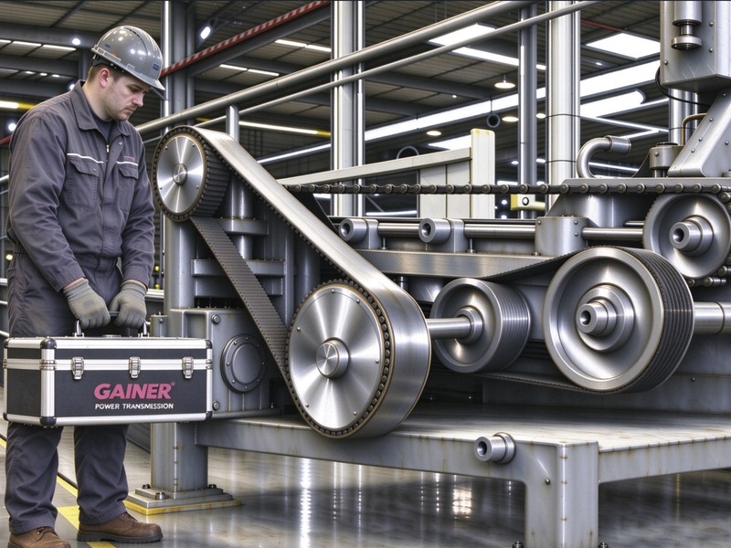
Flexible drive systems, including belt drives and chain drives, are widely applied in industrial equipment such as fans, pumps and conveyors. Owing to the shock‑absorbing and slight fault‑tolerant properties of flexible components, field maintenance personnel often hold a misconception that such drives do not require precise alignment. Numerous engineering cases have proven that misalignment is a critical factor contributing to premature failure of belts, chains and bearings, and it also gives rise to increased vibration, noise and higher transmission energy consumption. This paper sorts out misalignment types, inspection‑and‑calibration technologies and tolerance specifications for flexible drives, investigates equipment reliability and carbon‑reduction benefits brought by precision alignment, and introduces the GAINER laser belt‑pulley alignment tool series as an engineering solution for on‑site precision calibration.
1. Introduction to Flexible Drives
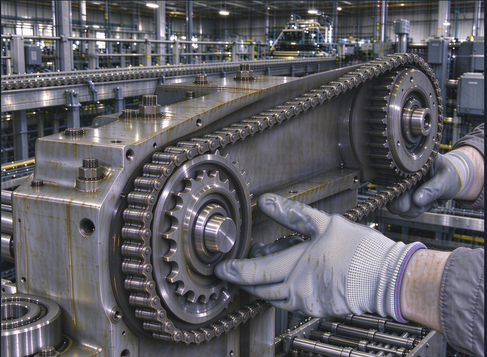
Flexible drives are mainly divided into two categories: belt drives and chain drives. Belt drives transmit torque by friction (toothed timing belts adopt meshing transmission), featuring shock absorption and easy installation. Chain drives realize power transmission through meshing between sprockets and chains, delivering stable transmission ratio and suitable for heavy‑duty working conditions. Both types can only tolerate minor parallel offset and angular misalignment. Once exceeding the allowable range, continuous lateral force will be generated, accelerating wear of transmission components and fatigue damage of bearings.
2. Misalignment Types and Failure Mechanisms
Misalignment of flexible‑drive wheel assemblies is mostly compound deviation consisting of angular misalignment and parallel offset. Lateral force induced by misalignment will result in:
- Unilateral wear of transmission components, uneven abrasion of pulley grooves and sprocket tooth surfaces;
- Bearings subject to additional radial loads with drastically reduced fatigue life;
- Elevated system vibration and noise;
- Increased frictional loss and consequent useless energy consumption.
3. Inspection and Calibration Technologies for Alignment
The core objective of flexible‑drive alignment is to keep driving and driven wheels axially parallel and coplanar, so as to eliminate parallel offset and angular misalignment. On‑site calibration methods fall into two categories: conventional mechanical rough measurement and laser‑aided precision measurement.
3.1 Conventional Visual / Mechanical Alignment (Rough Alignment, Low Precision)
Straight‑edge / Steel‑ruler Alignment Method
Attach a straight‑edge to the side end faces of two wheels and judge face flatness by visual observation.
Advantages: Easily‑accessible tools, simple operation
Disadvantages: Only applicable for small‑diameter wheels with short centre‑to‑centre distance; measurement error amplifies for large‑diameter wheels and long spans; angular misalignment cannot be quantified and it is merely for rough‑alignment reference.
Steel‑wire / Pull‑wire Alignment Method
Stretch a steel wire along the reference of wheel end faces and observe gap variation between steel wire and wheel surfaces.
Advantages: Applicable for wheel assemblies with relatively long centre‑to‑centre distance
Disadvantages: Steel wire deflects under self‑weight; human reading error exists, making it hard to obtain quantified deviation values.
Application scenario: Preliminary alignment for new‑equipment installation. Precision measuring instruments are still recommended for re‑inspection after rough alignment.
3.2 Laser Alignment Tool Calibration (Precision Alignment, Mainstream in Modern Industry)
The laser alignment tool adopts magnetic mounting to fix transmitter and receiver targets on wheel surfaces. It projects a laser reference beam to measure angular misalignment and parallel offset in both horizontal and vertical planes in one pass. Quantified deviation values are obtained to guide technicians to adjust motor shims for precision alignment.
Technical features: Not limited by wheel diameter, pulley‑groove profile or sprocket tooth profile; equipped with a 360° circular spirit level to assist instrument positioning and reduce initial measurement error caused by installation; measured data can be archived and conducive to implementing preventive‑maintenance systems.
Workflow: Rough alignment → Mount laser measurement units → Read deviation data → Adjust motor shims → Recheck alignment status → Set belt tension / chain sag → Re‑inspect after trial run to compensate position shift caused by thermal expansion.
Application scenario: Critical transmission equipment for continuously‑running pumps, fans and production lines, applied for energy‑saving improvement and preventive maintenance.
3.3 Alignment Tolerances
During calibration of flexible‑drive wheel assemblies, both angular misalignment and parallel offset shall be considered. Tolerances should be distinguished between recommended values and limit values. Recommended values shall be prioritized for critical production equipment.
Belt Drives
- V‑belt pulley: Angular misalignment limit: 0.5°
- Timing belt pulley: Angular misalignment limit: 0.25°
Chain Drives
The recommended angular value for sprockets is within 0.1°~0.2°, which represents the ideal range for long‑term stable operation.
Minor misalignment (<0.2°): Unilateral sprocket‑tooth wear and implicit service‑life loss; inner chain links engage with tooth surfaces laterally, triggering local stress concentration and continuous abrasive wear.
Moderate misalignment (0.2°~0.5°): Chain jamming, tooth climbing, aggravated vibration and noise; lateral load compresses fitting clearance between inner and outer link plates, raising rotational damping of hinge pairs and generating periodic impact load during meshing.
Severe misalignment (>0.5°): Chain seizure, tooth jumping and sudden chain‑breakage failure; persistent lateral load forces outward deformation of inner link plates, leading to plastic elongation of chain links and permanent pitch extension, thus forming a vicious cycle of meshing dislocation. When
Follow Us
Please add my ID to follow.
gh_8345cfafd08a